Product Selection Guides
Not sure which connector type fits your application? Start here.
Guide
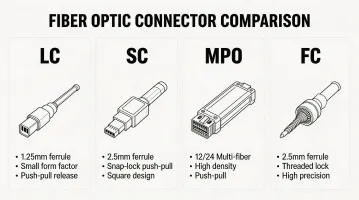
Fiber Optic Connector Selection Guide
Compare LC, SC, MPO, FC, and ST connectors by insertion loss, density, ease of termination, and cost per port. Includes a decision flowchart for common applications.
Download PDF →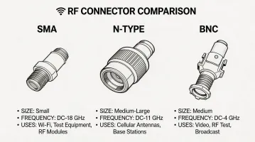
Guide
RF Connector Selection Guide
SMA, N-Type, BNC, TNC, and 7/16 DIN compared by frequency range, power handling, impedance, and environmental rating. Includes application mapping for each interface.
Download PDF →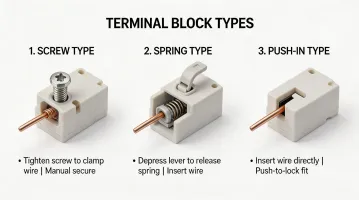
Guide
Terminal Block Selection Guide
Screw-clamp, spring-cage, and push-in designs compared by wire range, current rating, vibration resistance, and installation speed. Mounting options covered.
Download PDF →